 HOME
HOMEhydro testers
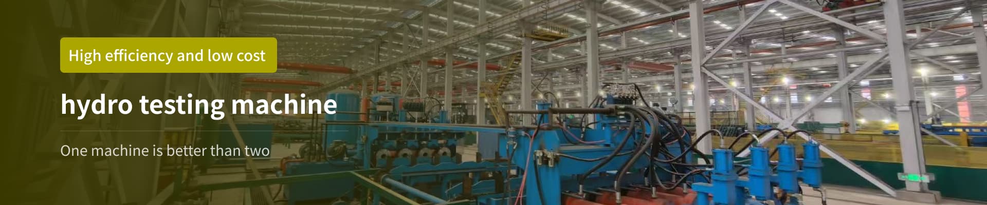
hydro testers
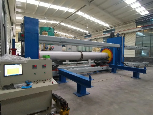
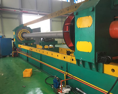
I:hydro testers Application and Structure
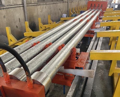
1.1 hydro testers Application: Used for combined hydrostatic testing of steel pipes.
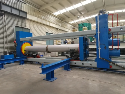
1.2 hydro testers Type: Single-station four-beam type with end-face seals.
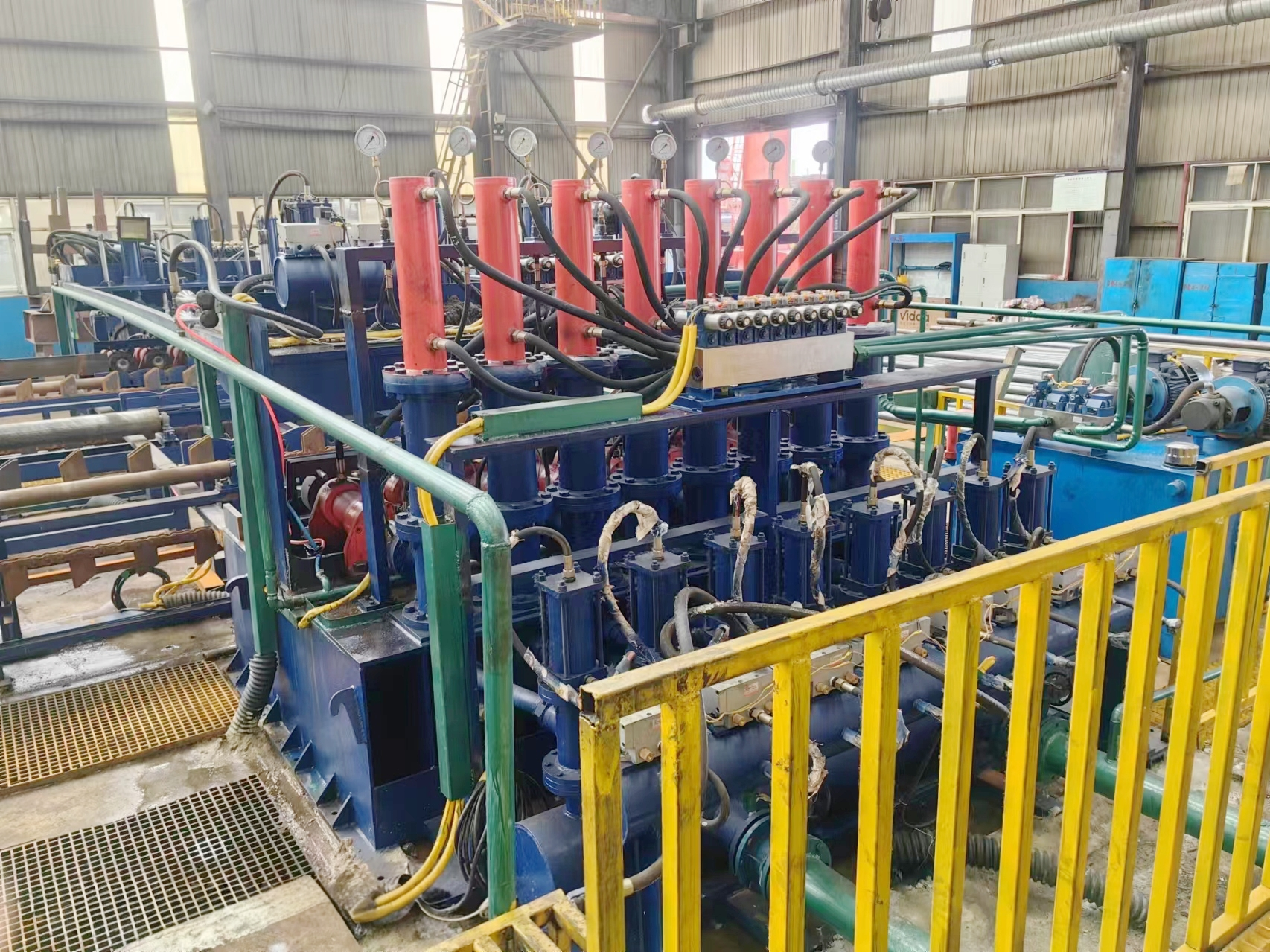
1.3 hydro testers Main Components: Tensile beam, movable test head assembly, lifting roller, test head, fixed test head assembly, hydraulic pusher assembly, low-pressure water system, booster system, large and small hydraulic stations, and PLC electronic control system.
Main Performance Parameters: The following are the parameters of an example steel pipe hydrostatic testing machine.
3500 tons/% 1460 Type
Steel Pipe Diameter (Inner Diameter) Range: 159 to 1422 mm (Corresponding Wall Thickness Range: 5 to 20 mm (Corresponding Diameter Range: Same as above)
Steel Pipe Length Range: 6 to 12 meters
Steel Pipe Materials: Carbon Steel and Stainless Steel; S235/S355/20#/Q345r/Q345b/304/316L, etc.
(Special Orders: Spiral Welded Pipe/Seamless Pipe/Seamless Pipe/Stainless Steel Seamless Pipe/Stainless Steel Welded Pipe)
Main Cylinder Thrust: 3500 tons (Triple Cylinder Type)
Sealing Method: End Seal
Sealing Plate Material: Rubber
Dwell Time: 4 to 6 seconds
Steel Pipe Materials: 20#/Q345r/Q345b/304/316L, etc. Composite and test pressures are calculated using the standard formula: P = 2SR/D. Calculation Example: For example, in the composite production of 400 steel pipe, the pressure P is calculated as: P = 2SR / D. The steel pipe wall thickness S = 10mm, the allowable stress R of No. 20 steel pipe is 137 MPa (at room temperature), and the outer diameter of the steel pipe is 400mm. Therefore, P = 2SR / D = 2 × 10 × 137 ÷ 400 = 6.85 MPa.
For special orders of spiral welded pipe/slotted steel pipe, the composite pressure and test pressure calculation formulas must be specified separately at the time of order.
Pressure Boosting Method: High-pressure Pump
Test Medium: Emulsion or tap water with corrosion inhibitor
Power Supply Customized
Control Power Supply Customized
II. Introduction to the Main Components of the Hydrostatic Pressure Tester:
2.1 Hydrostatic Pressure Tester Tensile Beams
Four rectangular beams measuring 500 × 300 × 20 × 15000 mm can be connected to a movable test head for varying pipe lengths from 6000 to 12500 mm.
2.2 Hydrostatic Test Machine Mobile Test Head Assembly
Includes the mobile end, travel drive, and other components.
The travel portion is driven by dual hydraulic cylinders.
The fixed end is equipped with an air release valve, which is opened and closed by the hydraulic cylinder.
2.3 hydro testers Lifting Roller
The lifting roller is driven by a hydraulic cylinder and guided by dual guide rods.
2.4 hydro testers Fixed Test Head Assembly
Includes high- and low-pressure air intake and exhaust relief valves, a hydraulic cylinder-driven DN100 controllable valve, and a pressure transmitter.
2.5 hydro testers Low-Pressure Water System
Includes a submersible pump, a low-pressure water valve, and a piping system. When the steel pipe is filled with water, the low-pressure water seal valve closes.
The low-pressure drain valve is opened and closed by the hydraulic cylinder.
2.6 Hydrostatic Test Machine High-Pressure Water System
Includes a high-pressure plunger pump, a check valve assembly, a pressure transmitter, and high-pressure piping.
After the air in the pipe is exhausted through the exhaust valve, a high-pressure plunger pump continuously pumps water into the pipe to increase the water pressure.
When the pipe pressure reaches the required level, pressure is stopped and the pipe pressure is relieved over a period of time, controlled by a pressure transmitter, smartwatch, and computer.
2.7 hydro testers Hydraulic System Description
2.7.1 hydro testers System Overview:
The main cylinder hydraulic system of the hydro testers is equipped with a separate hydraulic station.
One set of auxiliary cylinder hydraulic pump stations and nine hydraulic valves (cylinder push, cylinder push, mobile terminal rapid movement, left lifting roller, right lifting roller, pipe lateral movement, pipe blocking lifting, high-flow low-pressure hydraulic control valve, and single electric pressure relief and exhaust).
All hydraulic components are brand-name, and the internal valve core of the key check valve is made of stainless steel. This technology solves the problem of rusting when the check valve is used with water as the medium. It is a domestic and international first, and a patent has been applied for.
2.7.2 hydro testers Operation:
For the first combined pressure test, start the oil pump motor and adjust the pressure from low to high according to the pressure required by each component. Then, operate each cylinder one by one without load. Only after the operation is correct can the material feeding operation be carried out. If the pressure is insufficient during operation, it can be slowly increased, but it must not exceed the maximum pressure of the system. Subsequently, the oil pump motor should be started. Each combined pressure test and pressure test can only be carried out after the hydraulic system is normal.
Related Products