 HOME
HOMEpipe hydrotest machine
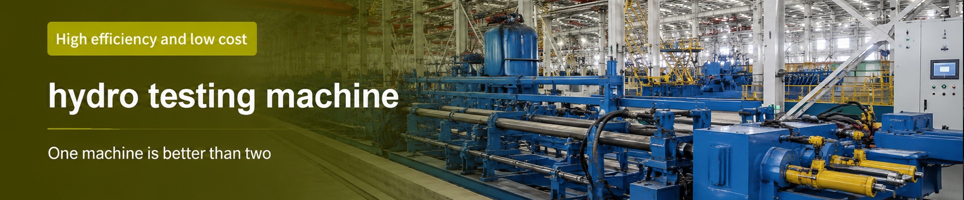
hydro testing machine
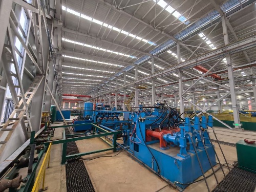
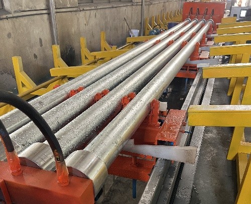
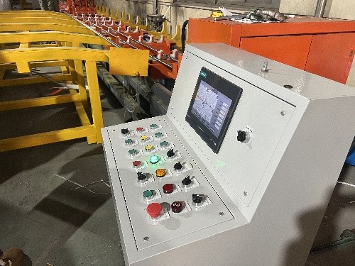
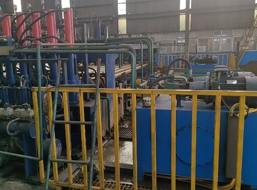
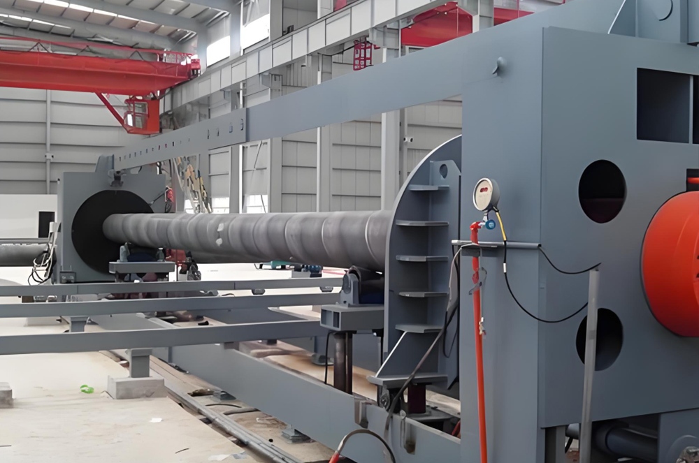
The hydro testing machine for pipe is designed for semi-automatic and fully automatic hydrostatic testing of steel pipes, stainless steel pipes, copper pipes, U-shaped pipes, and heat exchanger pipes. The system can handle pipe diameters starting from 6 mm, pipe lengths from 500 to 20,000 mm, wall thicknesses from 1 to 30 mm, and test pressures up to 300 MPa. Machine configuration can be customized according to pipe dimensions, testing requirements, production capacity, and required automation level.
Basic Specifications
|
Parameter |
Specification |
|
Equipment Type |
Semi-automatic or fully automatic hydrostatic testing machine |
|
Applicable Pipes |
Steel pipes, stainless steel pipes, copper pipes, U-shaped pipes, and heat exchanger pipes |
|
Pipe Diameter |
6 mm and above |
|
Pipe Length |
500–20,000 mm |
|
Wall Thickness |
1–30 mm |
|
Maximum Test Pressure |
Up to 300 MPa |
|
Dwell Time |
Approximately 5–10 seconds |
|
Testing Medium |
Water |
|
Control System |
PLC-based control system |
|
Pressure Display |
50-inch pressure curve display |
|
Remote Monitoring |
Available according to configuration |
Actual specifications may vary according to the final machine configuration and testing requirements.
Pipe Types for Hydrostatic Testing
The equipment can be configured for hydrostatic pressure testing of different pipe products, including:
- Steel pipes
- Stainless steel pipes
- Copper pipes
- U-shaped pipes
- Heat exchanger pipes
- Seamless steel pipes
- ERW steel pipes
- Welded steel pipes
- Large-diameter pipes
- Industrial and pressure pipes
The sealing system, pressure system, pipe handling system, and testing cycle can be configured according to the characteristics and production requirements of the pipe being tested.
Hydrostatic Testing Process
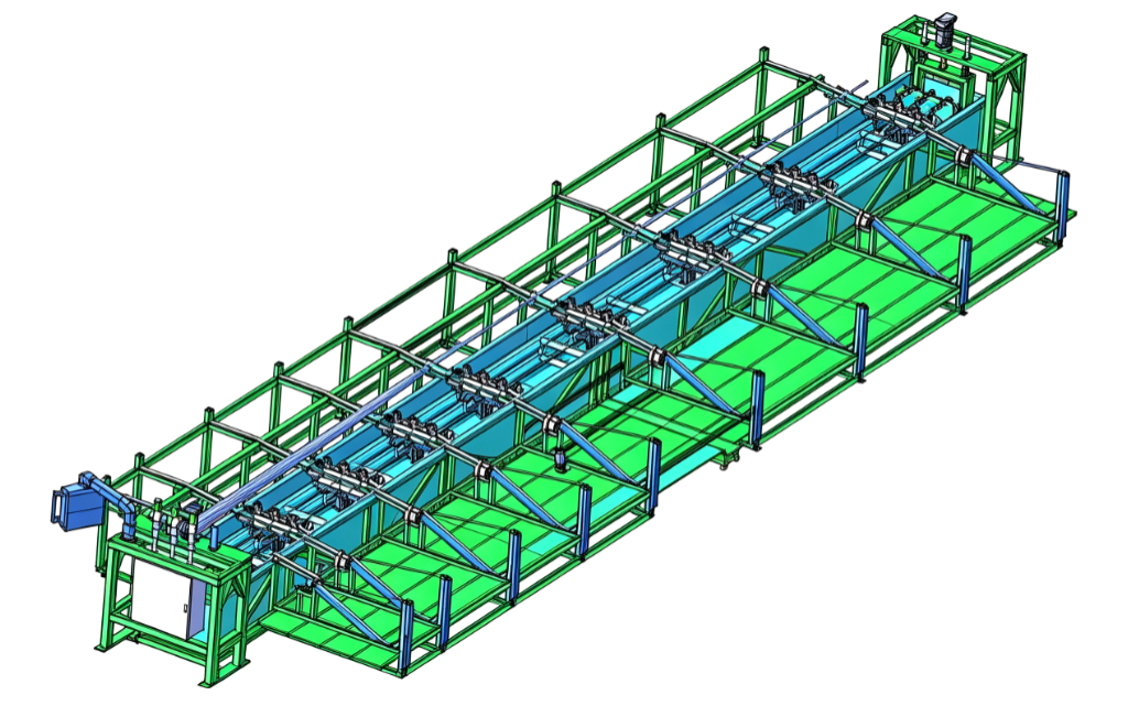
The pipe hydrostatic testing system integrates pipe transfer, positioning, water filling, air venting, pressurization, pressure holding, pressure relief, water drainage, and unloading into a controlled testing sequence.
1. Pipe Transfer
The pipe is transferred into the testing position through the transverse movement system. Chain conveyors and related mechanisms move the pipe between the feeding, cleaning, testing, and unloading positions.
2. Internal Pipe Cleaning
A pressurized-water cleaning process can be integrated into the transverse transfer operation to clean the inside of the steel pipe.
The cleaning operation can be arranged so that it does not add to the main internal testing cycle time.
3. Pipe Positioning and Jacking
The pipe is positioned in the testing station using the pipe jacking system. Hydraulic cylinders and positioning mechanisms move the pipe into the required testing position.
4. Water Filling
The water injection valve opens and the pipe is filled with the testing medium. The water injection system consists of the water pump, energy storage tank, water injection valve, and air release valve.
5. Air Venting
Air inside the pipe is released through the air-release system before pressure is increased. Proper air removal helps maintain stable hydrostatic testing conditions.
6. Pressurization
After filling and venting, the hydraulic pressure system increases the internal pipe pressure to the specified test pressure.
The system can be configured for test pressures up to 300 MPa, depending on the final machine configuration.
7. Pressure Holding
Once the required test pressure is reached, the system maintains the pressure for the specified dwell period.
The standard dwell time is approximately 5–10 seconds, subject to the testing requirements and final machine configuration.
8. Pressure Relief and Water Drainage
After the pressure-holding stage, the system releases the internal pressure in a controlled sequence and drains the testing water from the pipe.
9. Seal Release and Pipe Transfer
After pressure has been safely released and the testing sequence is completed, the sealing system is released and the pipe is transferred to the next production position.
Testing Cycle Time
The complete testing cycle depends on pipe dimensions, test pressure, machine configuration, and production requirements.
Based on the current configuration, the shortest total cycle time is approximately 45 seconds, while the maximum cycle time is approximately 80 seconds.
|
Operation |
Minimum Time |
Maximum Time |
|
Transverse Transfer |
10 s |
15 s |
|
Pipe Jacking |
5 s |
5 s |
|
Steel Pipe Water Filling |
5 s |
20 s |
|
Steel Pipe Air Venting |
2 s |
5 s |
|
Pressurization |
3 s |
5 s |
|
Pressure Holding |
5 s |
10 s |
|
Pressure Relief |
5 s |
5 s |
|
Water Drainage |
5 s |
5 s |
|
Back Jacking / Test Head Release |
5 s |
10 s |
|
Total Cycle Time |
45 s |
80 s |
The internal cleaning process can be arranged without occupying the main internal testing cycle time. Actual cycle time depends on the pipe specification, test pressure, testing procedure, and machine configuration.
Equipment Components
The pipe hydrostatic testing machine consists of several integrated systems for water filling, pipe positioning, sealing, pressure generation, pipe transfer, hydraulic control, and automatic operation.
1. Water Injection System
The water injection system supplies the testing medium to the pipe and can be customized according to the required testing configuration.
Main components include:
- Water pump
- Energy storage tank
- Water injection valve
- Air release valve
- Associated water piping and control components
The water system is designed to provide stable and controlled water filling before the pressurization stage.
2. Pipe Jacking and Sealing System
The pipe jacking system positions the pipe and supports the sealing process during hydrostatic testing.
The system can include:
- Pipe jacking box
- Hydraulic cylinders
- External-diameter sealing test head
- Internal-diameter sealing device
- Test-head tips
- Customized sealing components
Sealing components can be individually manufactured or customized according to pipe diameter, pipe-end condition, test pressure, and customer requirements.
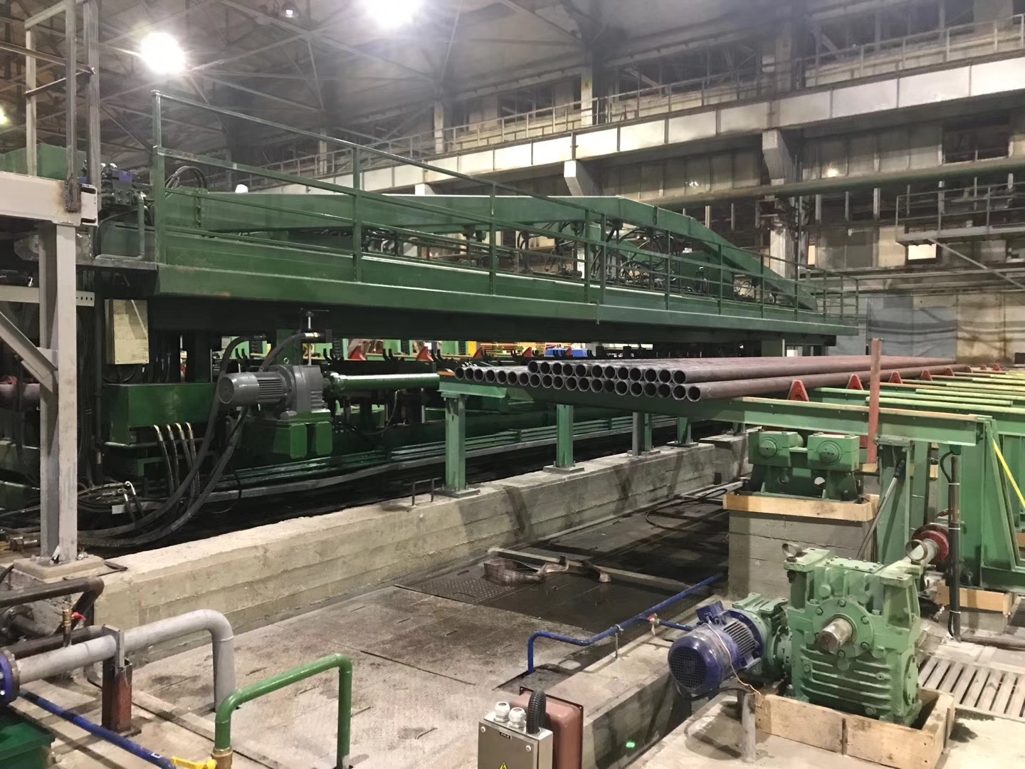
3. Transverse Pipe Movement System
The transverse movement system transfers pipes between different operating positions.
The system uses chain-based conveying mechanisms to move pipes through the feeding, cleaning, testing, and unloading stages.
Depending on the machine configuration, the transverse system can coordinate:
- Pipe feeding
- Pipe positioning
- Internal water cleaning
- Pipe transfer
- Water drainage
- Pipe unloading
4. Pipe Cleaning System
The equipment can incorporate a pressurized-water cleaning process into the pipe transfer sequence.
This system uses pressurized water to clean the internal surface of the steel pipe before or during the material-transfer process.
The cleaning operation is designed to work alongside the main testing sequence without unnecessarily increasing the internal testing cycle.
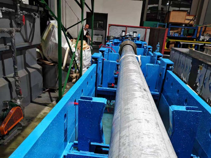
5. Machine Bed and Pipe Handling System
The machine bed supports the feeding, testing, transfer, and unloading operations.
The pipe handling system can be configured to:
- Feed pipes into the testing station
- Position pipes accurately
- Transfer pipes between stations
- Remove tested pipes
- Coordinate with upstream and downstream production equipment
The layout can be customized according to the available production-line space and required material flow.
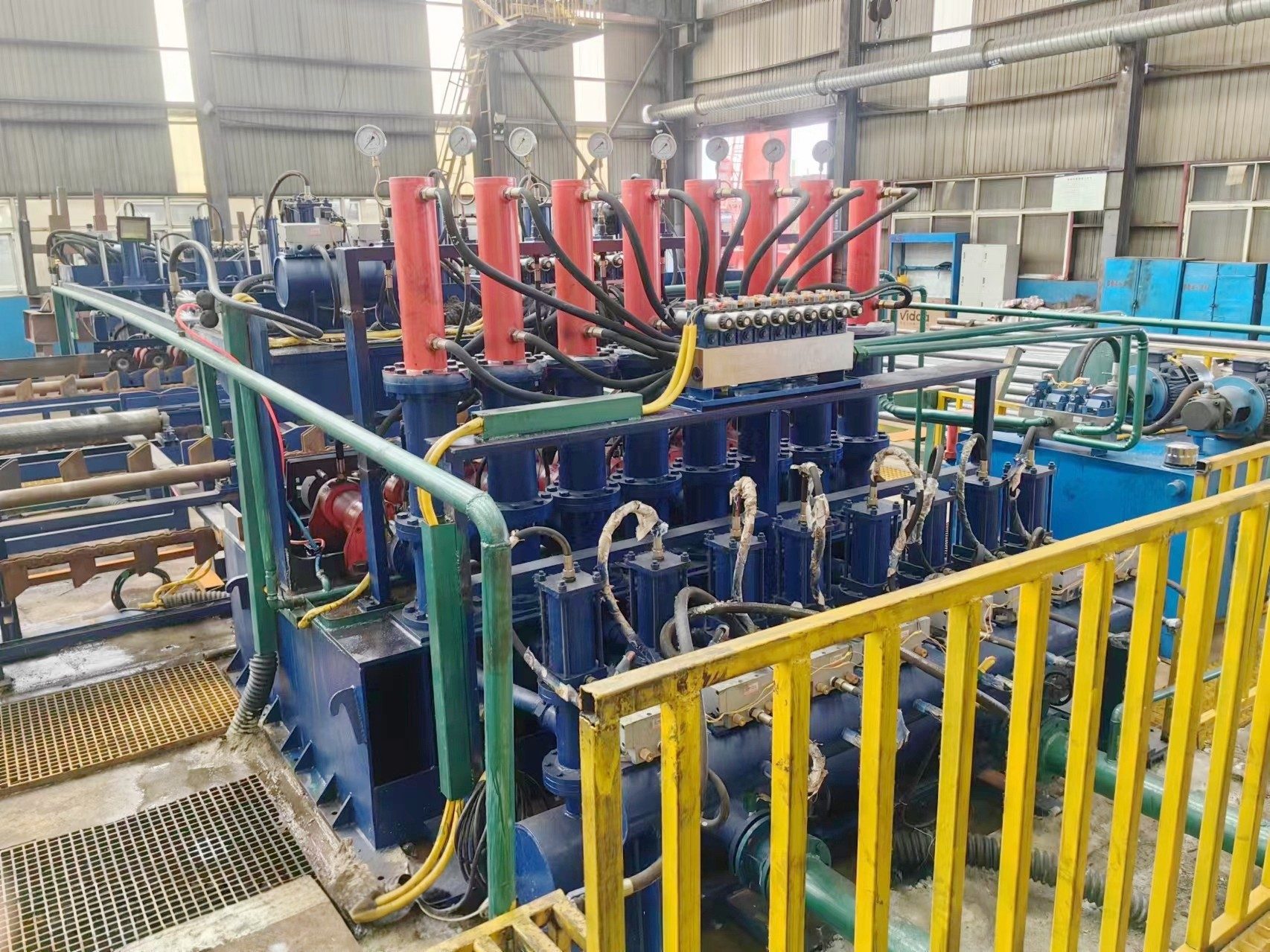
6. Hydraulic System
The hydraulic system provides the power required for pipe jacking, positioning, clamping, and pressure-related operations.
The system can include:
- Hydraulic power unit
- Pipe jacking cylinders
- Clamping cylinders
- Booster cylinders
- Push-baffle cylinder
- Hydraulic valves and control components
The hydraulic configuration is selected according to pipe size, machine configuration, operating cycle, and required testing pressure.
7. Control and Monitoring System
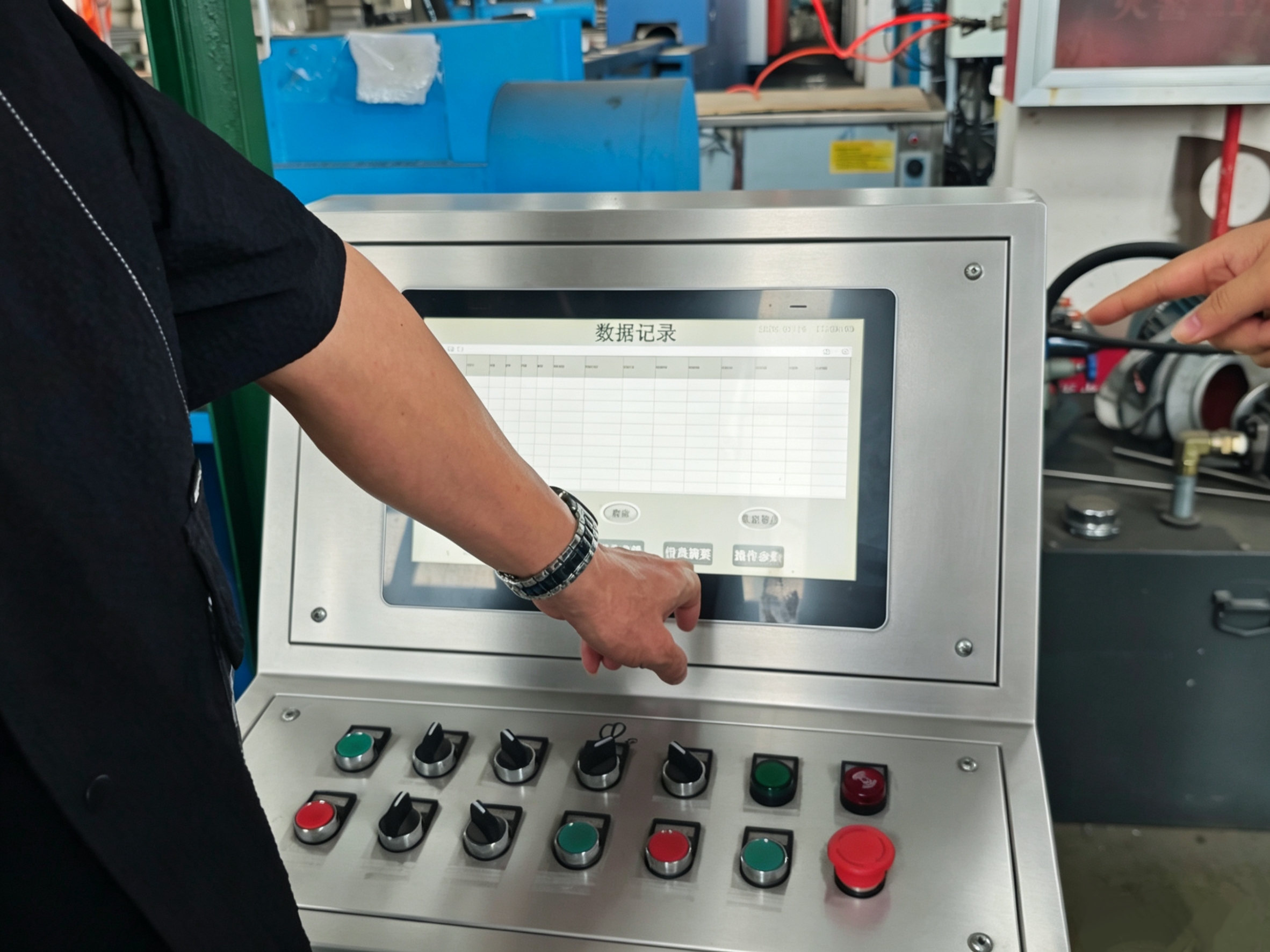
The control system manages the main operating sequence of the hydrostatic testing machine.
The standard configuration can include:
- Operating console
- Electrical power cabinet
- PLC control system
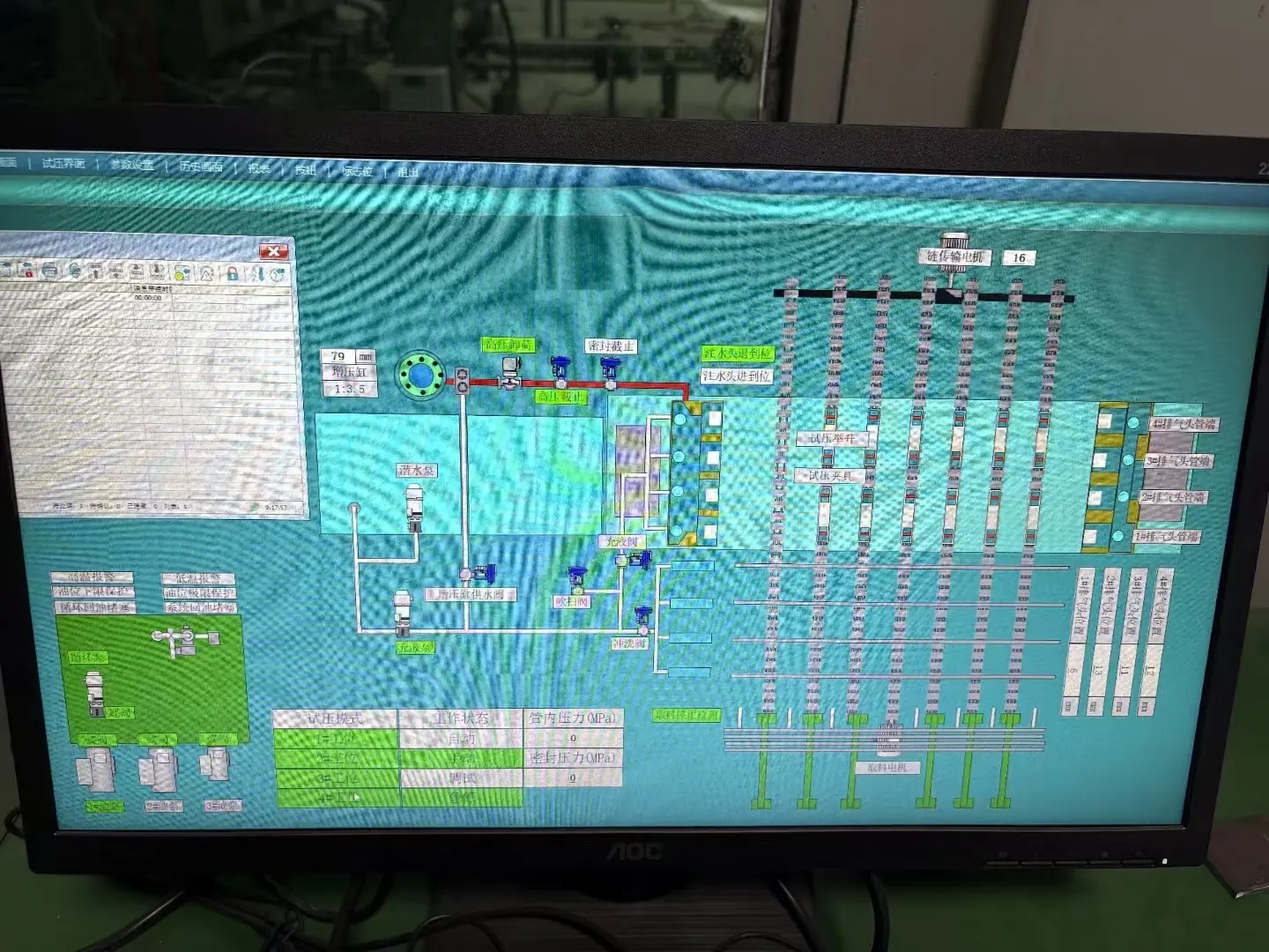
- 50-inch pressure curve display
- Pressure monitoring
- Remote monitoring system
The PLC-based control system coordinates the testing sequence from pipe positioning and water filling through pressurization, pressure holding, pressure relief, and unloading.
The pressure curve display allows operators to monitor the pressure condition during the testing process.
Operating Principle
The basic operating sequence of the machine is:
Water storage → Transverse pipe movement → Internal cleaning → Transverse movement → Pipe jacking → Water filling → Air venting → Pressurization → Pressure holding → Pressure relief → Water drainage → Seal release → Test-head retraction → Transverse pipe movement
The water pump continuously supplies the energy storage tank with water. Once the pipe reaches the testing station, the positioning and sealing systems secure the pipe before water filling begins.
After the pipe is filled and air is released, the hydraulic pressure system raises the internal pressure to the specified test value. The system then maintains the pressure for the required dwell time before completing the pressure-relief and drainage sequence.
The PLC control system coordinates the complete process to provide a repeatable testing cycle.
Main Component Configuration
|
Components |
Name |
Model |
Quantity |
|
Feeding rack 1 |
Cylinder φ125X200 |
trunnion type |
2 |
|
Water system |
Water pump (flow 100, lift 64m, power 22KW, speed 2900r/min) |
KBW100/200-22/2 |
2 |
|
Feeding rack 2 |
Cylinder φ125X200 |
trunnion type |
2 |
|
discharge bench |
Cylinder φ125X110 |
JB125X110-B |
4 |
|
Conveyor chain |
Transverse chain conveyor motor |
Y112M-4 4KW,1500 r/min |
1 |
|
Transverse conveyor chain |
Standard roller chain section 40A84 |
5 |
|
|
Transverse drive chain |
Standard roller chain 16A120 section |
1 |
|
|
Reducer for traverse chain |
XWD6-59-4 |
1 |
|
|
Clamping cylinder |
φ140x420 |
|
14 |
|
Item pipe cylinder |
ø140/80-150, tripod installation |
|
8 |
|
Booster cylinder |
ø125X400, front flange mounting |
|
4 |
|
Push the baffle cylinder |
φ160X200 |
|
1 |
|
Rotating roller reduction motor |
XWD4-35-1.5 |
Cycloidal pin reducer belt AC motor 4-pole |
7 |
Application in Steel Pipe Production Lines
The equipment can be integrated into steel pipe production and finishing lines where hydrostatic pressure testing is required.
Typical applications include:
- Line pipe production
- Large-diameter welded pipe production
- ERW pipe production
- Seamless pipe production
- Pressure pipe manufacturing
- Oil and gas pipe production
- Industrial steel pipe manufacturing
- Water transmission pipe production
The machine layout and pipe handling system can be adapted to the available production-line space and the required material flow between pipe forming, welding, inspection, hydrostatic testing, finishing, and storage processes.
Configuration for Different Pipe Testing Requirements
The configuration of a pipe hydrostatic testing machine should be determined by the actual pipe and production requirements rather than by maximum pressure alone.
Key factors include:
|
Requirement |
Effect on Machine Configuration |
|
Pipe Diameter |
Determines testing range, sealing size, and pipe handling |
|
Pipe Length |
Influences machine bed and transfer arrangement |
|
Wall Thickness |
Affects test pressure and pipe handling requirements |
|
Test Pressure |
Determines pressure-generation and hydraulic system requirements |
|
Dwell Time |
Influences the testing cycle |
|
Production Capacity |
Determines cycle time and number of testing stations |
|
Pipe Type |
Influences sealing and handling configuration |
|
Automation Level |
Determines the degree of automatic operation |
|
Pipe-End Condition |
Influences the selection of sealing components |
|
Production-Line Layout |
Determines machine arrangement and material flow |
A machine for high-volume ERW pipe production may require a different configuration from a system used for large-diameter welded pipes. Similarly, high-pressure testing requires appropriate pressure-generation, sealing, hydraulic, and safety configurations.
Product Configuration and Customization
The hydrostatic testing system can be customized according to the customer's pipe specifications and production requirements.
Before equipment design, the main engineering parameters normally include:
- Pipe diameter range
- Pipe length range
- Wall thickness
- Required test pressure
- Pressure holding time
- Pipe material
- Pipe-end condition
- Required production capacity
- Required testing cycle
- Automation level
- Available production-line space
- Pipe feeding and unloading requirements
Based on these parameters, the water injection system, sealing heads, hydraulic system, pipe handling equipment, testing stations, control system, and machine layout can be configured accordingly.
This customized configuration enables the equipment to match different steel pipe specifications, production capacities, and hydrostatic testing requirements.
Related Products