


 HOME
How to Reduce Pressure Overshoot During Pipe Hydrostatic Testing
21 October 2026
Pressure overshoot during pipe hydrostatic testing occurs when the measured pressure rises above the specified target before the system can stop or reduce pressurization. In a steel pipe hydrostatic testing machine, the most effective correction is usually to coordinate pump output, valve response and pressure-control logic rather than simply reduce pump capacity.
For steel pipe mills, including manufacturers of oilfield casing and tubing, the objective is to reach the required test pressure predictably, keep it within the applicable acceptance limits and avoid unnecessary mechanical loading. The correct solution depends on the hydraulic circuit, pipe dimensions, test pressure and production cycle.
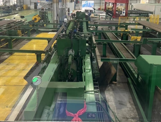
1. Identify Where the Overshoot Begins
The first step is to examine the pressure-time curve, not immediately change the PLC settings. Record the target pressure, peak pressure, time of the peak and controller output around the moment of overshoot. If available, compare the pressure signal with pump commands and valve-position feedback.
|
Observed pressure behavior |
Possible cause |
First engineering check |
|
Pressure rises smoothly, then peaks after the pump command decreases |
Pump flow and stored hydraulic energy continue affecting pressure |
Check pump response, flow rate and control-output timing |
|
Pressure overshoots sharply near the setpoint |
Controller tuning, excessive correction or control delay |
Reduce the final-stage ramp rate and verify valve response |
|
Pressure repeatedly rises and falls around the target |
Controller tuning, excessive correction or control delay |
Review control parameters, signal filtering and system response |
|
Overshoot varies significantly between cycles |
Inconsistent filling, air removal, sealing or operating conditions |
Compare pipe setup and pressure curves across repeat tests |
|
Displayed pressure spikes without a corresponding process change |
Sensor, wiring, signal noise or acquisition problem |
Verify the pressure transmitter and measurement chain |
These patterns are diagnostic clues, not definitive diagnoses. A pressure curve should be interpreted alongside equipment signals and physical checks.
2. Reduce the Pressure Ramp Before the Target Is Reached
A common cause of overshoot is continuing to deliver water at a high rate as the system approaches its target pressure. By the time the controller detects that the setpoint has been reached, the pump and valve may not respond instantly. Pressure can therefore continue rising.
A practical approach is to use staged pressurization where the machine design permits it:
-
Initial pressurization: Build pressure at a rate suited to the pipe volume and hydraulic circuit.
-
Approach stage: Reduce the flow rate before reaching the target.
-
Final adjustment: Use smaller control corrections to approach the setpoint without repeated overshoot.
-
Holding stage: Maintain pressure within the required limits using the approved control sequence.
The transition point between stages should be established during commissioning, based on recorded pressure behavior. It should not be copied blindly from another machine because pump characteristics, pipe dimensions and circuit response differ.
Reducing the ramp rate only near the target can often preserve much of the cycle-time advantage while improving pressure control. Slowing the entire cycle unnecessarily may reduce production output without addressing the actual cause.
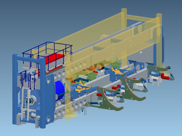
3. Match Pump and Valve Response to the Control System
Pressure control depends on the interaction between the pump, regulating valves, pressure transmitter and PLC. Improving one component will not necessarily solve a problem caused elsewhere in the loop.
|
Component or setting |
Recommended action |
Why it matters |
|
High-pressure pump |
Verify flow characteristics and response to stop or speed commands |
Excess flow near the target can drive continued pressure rise |
|
Proportional or regulating valve |
Check response time, sticking, sizing and control direction |
Delayed or inconsistent flow adjustment can cause overshoot |
|
Pressure transmitter |
Verify calibration, range, installation and signal stability |
Incorrect feedback leads the controller to make inappropriate corrections |
|
PLC control logic |
Review ramp stages, output limits, response delays and control parameters |
Excessive correction or late intervention can destabilize pressure |
|
Pressure measurement and recording |
Compare recorded values with a suitable reference instrument |
Confirms whether the overshoot is real or caused by the measurement chain |
Where PID control is used, tuning should be based on the actual response of the complete pressure-control loop. Excessive proportional action can produce aggressive corrections; excessive integral action may contribute to overshoot when the actuator is saturated or response is delayed. However, changing PID values without first checking hardware response, signal quality and control logic can make the problem worse.
Not every pipe hydro testing machine uses the same control architecture. The appropriate adjustment may involve variable pump speed, a regulating valve, staged control logic or a combination of these, depending on the equipment design.
4. Check Filling, Air Removal and Sealing Conditions
Control tuning cannot compensate reliably for an inconsistent test setup. Residual air changes the compressibility of the water-filled system and can alter pressure response. Incomplete filling, unstable end sealing or leakage may also produce pressure curves that vary from one cycle to another.
Before changing control parameters, confirm that:
-
The pipe and relevant test circuit are filled according to the approved procedure.
-
Air is removed from locations where it can remain trapped.
-
The end-sealing assembly is correctly positioned and does not move under pressure.
-
Valves operate consistently and the high-pressure circuit has no unintended leakage.
-
The pipe dimensions and test setup match the selected recipe.
For an OCTG hydrostatic testing machine, changes in casing or tubing dimensions and end geometry can affect sealing and system response. Product changeovers should therefore be included in pressure-control verification rather than assuming that one setting will perform identically across the entire product range.
5. Verify the Improvement With Repeatable Tests
A single successful pressure cycle does not prove that the problem has been resolved. After making an adjustment, compare the pressure curves from repeated tests under equivalent conditions.
Useful indicators include peak pressure above setpoint, time required to stabilize, pressure variation during the holding stage and cycle-to-cycle consistency. The allowable limits must come from the applicable inspection procedure, customer requirements and equipment acceptance criteria; there is no universal overshoot percentage suitable for every application.
For a customized steel pipe hydrostatic testing machine, these checks should be included in commissioning and, where relevant, repeated after changes to the product range, control settings or hydraulic components. Pressure relief devices and other safety protections must remain correctly configured and must never be bypassed to improve cycle time.
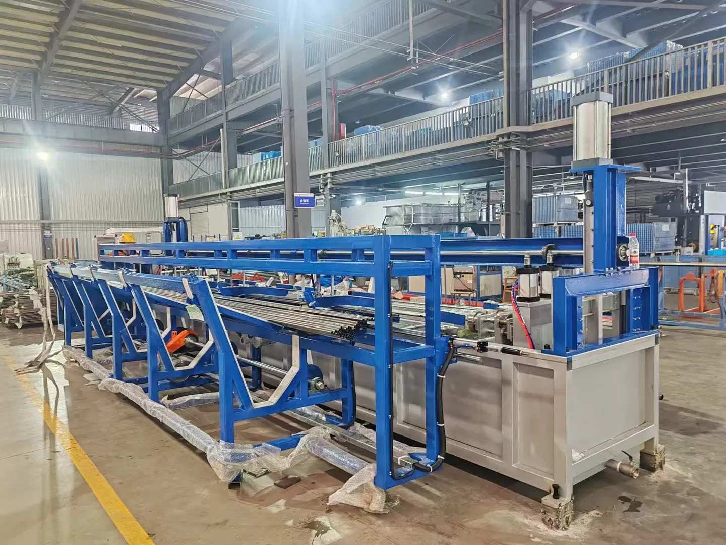
Reducing pressure overshoot requires a systematic approach: analyze the pressure curve, reduce excessive flow near the target, verify pump and valve response, check measurement accuracy, and confirm consistent filling and sealing conditions.
For manufacturers of casing, tubing and other steel tubular products, a well-matched pipe hydrostatic testing machine should be configured around the required pressure range, product dimensions, control response and production needs. The goal is not merely to reach the setpoint quickly, but to achieve repeatable pressure control without compromising test integrity or equipment safety.


